
Solar inverters or charge controllers use maximum power point tracking (MPPT) to get the maximum possible power from the PV array.
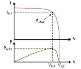
Solar cells have a complex relationship between solar irradiation, temperature and total resistance that produces a non-linear output efficiency known as the I-V curve. It is the purpose of the MPPT system to sample the output of the cells and determine a resistance (load) to obtain maximum power f or any given environmental conditions.
Essentially, this defines the current that the inverter should draw from the PV in order to get the maximum possible power (since power equals voltage times current).
Working Principle of Maximum Power Point Tracking:
A Maximum Power Point Tracking solar regulator will simulate the load required by the solar panel to achieve the maximum power from the cell. The regulator will work out at which point the cell will output the maximum power and derive from this the voltage and current outputs required for maximum power to be achieved. It will then calculate the load that it must simulate based on these voltage and current levels R=V/I. The regulator, now receiving the maximum amount of power in, will then regulate the output according to what it is designed for.
In this image you can see that if we use a inverter which works without an MPPT algorithm, then the system become in-efficient or in other words there will be losses in utilizing the solar power. But we use an inverter which works on a MPPT algorithm then the utilizing of power is far better.
Now let's talk about the Fill Factor (FF) which is a very important and of course an integral part of the MPPT methodology.
The fill factor, more commonly known by its abbreviation FF, is a parameter which, in conjunction with the open circuit voltage and short circuit current of the panel, determines the maximum power from a solar cell. A solar micro-inverter in the process of being installed . The ground wire is attached to the lug and the panel's DC connections are attached to the cables on the lower right. The AC parallel trunk open circuit voltage and short circuit current of the panel, determines the maximum power from a solar cell. Fill factor is defined as the ratio of the maximum power from the solar cell to the product of Voc and Isc.
So, the mathematical expression of Fill Factor is FF=(Imp x Vmp) / (Isc x Voc)
Benefits By Using MPPT Based Devices In Solar PV System
MPPT ensures that you get the most power possible from your solar panels at any point in time. It is particularly effective during low light level conditions. These calculations result in an output that delivers maximum current at the required voltage at any point in time. During low light level situations it will compensate for the low light level and find the new point at which the solar cell delivers its maximum power output.


